Rustic Retreat
Hot Projects
Live broadcasts and documentation from a remote tech outpost in rustic Portugal. Sharing off-grid life, the necessary research & development and the pursuit of life, without centralized infrastructure.
 Subscribe to our new main project Rustic Retreat on the projects own website.
This is an old revision of the document!
| Attribute | Value | Schematics |
|---|---|---|
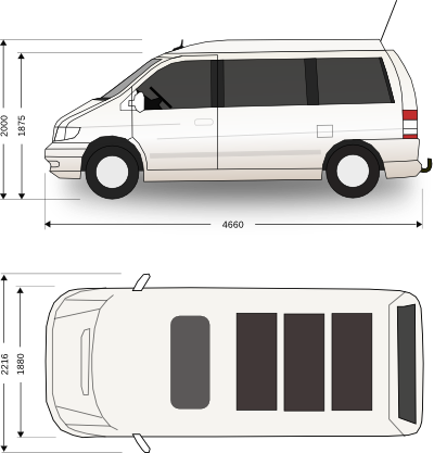
| Model | V 220 CDI |  |
| Motor | OM 611 DE 22 LA | |
| Capacity | 2148 cm³ | |
| Cylinder/Valves | R4/16 | |
| Power @ min-1 | 90 kW/3800 | |
| Torque @ min-1 | 300 Nm/1800–2500 | |
| Build | 2002 | |
| HSN | 0710 | |
| TSN | 558 |
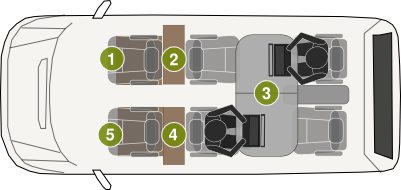
| 1 | Passenger Seat Eletronics |  |
| 2 | Battery + Charging EQ | |
| 3 | Retractable Table | |
| 4 | Control Units (PDU, SKU, MCU) | |
| 5 | Driver Seat Electronics |
The bulk of onboard systems is modularized into several units which reside in a half 19“ 3HE rack, using common DIN-EN/IEC 60603-2C connectors for in system power and signal distribution.
Each unit also carries a Dallas 18S20 digital temperature sensor, connected to the SKU's 1-Wire Bus for centralized temperature monitoring and to identify each module, since each sensor has a unique ID. That makes it possible to let the SKU know, which modules are present.
To reduce fuel consumption, all subsystems are powered by the secondary battery in order to minimize the power demand of the alternator on the primary engine.
A flexible configuration is only as good as the least flexible part of the chain. In order to keep future changes in mind, the system had to have a central power distribution unit and highly-efficient subsystem voltage converters. The PDU also acts as a monitoring device for the SKU on all relevant power in/outlet buses. See the pdu page for more details.
The purpose of the SKU is to monitor, analyze and control all of Odyssey's subsystems as well as to provide basic system features (i.e. GPS, Time, Networking, System-Watchdogs). It will also monitor and record habitual & mobile environmental (external/internal) sensor data, develop power consumption profiles to recommend either a change in power usage behaviour or a change in power harvesting methods to maximize efficiency. Read more on the sku page.
One of the bigger challenges in terms of power budget was the audio system. Having the ability to listen to music or other audio material seemed kind of essentiell and almost all current implementations of pre-amp/amp designs (Class A,B,A/B or D) were undesirable either due to power or audiophile constraints - they either drew too much power or the sound quality was totally inacceptable or both.
More details on the audio page.
Apollo-NG is designed to operate fully autonomous and self-sustainable in its function as a Hackerspace and also as habitat for crew and joining hackers. Each module (CM/LM) must be able to sustain and support itself and both modules are designed to share and work together when combined to increase efficiency and redundancy.
In order to reduce the risk of power unavailability and to inspire research on different energy conversion techniques it seemed reasonable to diversify:
Rational thinking will ultimately come to the conclusion, that increasing efficiency and diversity is not going to be enough to keep a fully self-sustainable and autonomous state. Therefore, all power consuming use cases and their underlying technology, have to be constantly monitored by the SKU and optimized to fit into the conservative power budget of 50W maximum consumption for 10 hours per day (500Wh/day).
Modern technology like LED's, embedded SoC devices and highly efficient switch-mode power supplies make this possible and have been developed/tested for the last 12 month.
| Nominal Peak Power | 110 Wp | 330 Wp |
| Short-circuit current | 6.1 A | 18.3 A |
| Idle-Voltage | 22 V | 22 V |
| Cells | 36 Mono | 108 Mono |
| Cell-Size | 13×13 cm | 140.4×140.4 cm |
| Panel-Size | 125x55x3.3 cm | 125x165x3.3 cm |
| Weight | 8.3KG | 24.9KG |
<note tip>The panel's surface is a little bit larger than the actual cell surface. The following calculations were based on a combined photo-active area of 1404x1404mm, by measuring and multiplying the size of a single cell. </note>
<x 14>1404*1404 = 1.971m²</x>
Assuming a maximum of 800W of energy per m2 delivered by the sun on the planet's surface, the Odyssey's available combined photo-active roof surface (1.971m²) can theoretically receive a maximum of 1577Wp (Watt Peak), in peak sunlight:
<x 14>1.971*800=1577Wp</x>
In peak sunlight, the Odyssey will receive about 1.5 kW of solar energy on all cells. The conversion efficiency for these modules is rated at 20% by the manufacturer. Knowing that, it's possible to calculate the maximum amount of power the Odyssey can harvest with her finite roof-space at 20% module efficiency. Of course, the cell efficiency will be slightly higher:
<x 14>1.971*800*0.2 = 315Wp</x>
Now for the sake of going through it, lets further assume a luxuriously sunny, clear-sky day and the opportunity to harvest 4 hours at maximum peak output, the solar power-budget will accumulate about 1260Wh (95Ah).
<x 14>315W * 4h = 1260Wh \approx 95Ah</x>
Although the panels will not stop converting energy after the peak four hours, the current will probably drop soon enough. As of now there is no data to conclude anything.
Real-World prototyping and testing of helios
A good way to harvest additional power to charge the battery would be to add TEG's to Odysseys's primary engine exhaust system, thereby increasing the overall efficiency of burning fuel without the need to burn even more fuel in contrast to harvesting power from the alternator.
In emergency situations or other irregular energy shortages a boost converter can charge the battery by harvesting power from the Odysseys's alternator. As this will increase the fuel consumption of the vehicle, it's only going to be used when absolutely necessary, i.e. when the battery is empty and the Odyssey is moving at night (no solar power).
The SKU will use navigation system data to predict how much driving time is needed to re-charge the battery to be operational on arrival and will then recommend to use the Votronic VCC 1212-25 IU boost converter to charge the battery, trying to balance the increased cost of fuel consumption.
The boost converter is needed to provide the necessary 14.4V charge voltage needed by the AGM battery to reach its maximum capacity.
AGM 270Ah