Rustic Retreat
Live broadcasts and documentation from a remote tech outpost in rustic Portugal. Sharing off-grid life, the necessary research & development and the pursuit of life, without centralized infrastructure.
 Subscribe to our new main project Rustic Retreat on the projects own website.
Hot Projects
SEEDStack
 DIY Food Hacking
UCSSPM
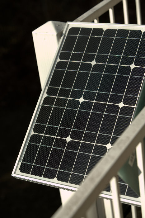
 Open Solar Power
picoReflow
 DIY Reflow Soldering
PiGI
 RasPi Geiger Counter
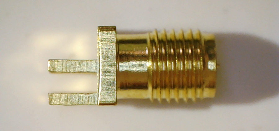
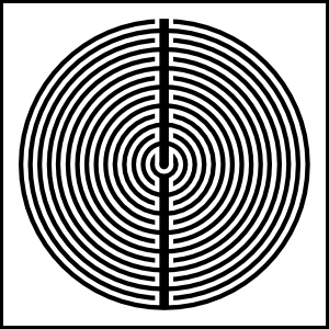
DIY ARA-2000
 Wideband Antenna
DSpace
 Map everything!
Mission-Tags
3d
3d-printer
antenna
development
diy
dspace
energy
events
fabrication
felix
geiger
geigercounter
gentoo
geo
gis
gnuradio
grc
hack
hardware
lab
linux
livestream
map
monitoring
odyssey
pi
picocnc
picofab
picoprint
pigi
power
printer
python
radiation
radio
raspberry
receiver
research
rf
robot
sdr
security
sku
software
solar
sponsor
test
voron
wind
zephyr