Table of Contents
picoReflow
More and more semiconductors are produced in packages (the chip's case) which have become impossible to hand solder with a solder iron. The switch from through-hole (THT) to surface mount technology (SMT) has actually made hand soldering much easier (although still many believe the opposite to be true) but now we are faced with BGA and other packaging forms which only have contacts on the bottom of the chip.
In order to be able to work with these chips, a reflow solder process is needed. So we've built our own DIY reflow oven, using a Raspberry Pi as a universal, web enabled, PID Reflow Oven Controller driving a convectional hot air oven originally designated for gastronomy/bakery purposes.
Since it's all open-source you may also use it to build a kiln controller, the world's most sophisticated pizza oven controller and experiment with temperature curves for fresh/frozen pizza and has also been reported to be used in other lab/production processing systems and autonomous climate testing.
Remember:
Never put food into an oven that you have used for reflow soldering purposes.
- Raspberry Pi
- Supported SPI driven Cold-Junction K-Type Thermocouple converter:
- MAX31855
- MAX6675
- GPIO driven Solid State Relays (230V heating/fan)
- PWM driven MOSFET (12V cooling)
- Python control daemon (running on the Pi)
- HTML5/Websocket OS independent multi user web-client
- Live Monitoring & control
- Browser based Profile/Curve Management + Slope Calculator
At this point (although still only a PoC-Demonstrator) the software is a fully functional PID controller and even incorporates a simulator, so you can try, play and extend the software without the need for real hardware. If the daemon doesn't find a thermocouple, it will automatically switch into simulation mode. It's still a little bit hackish and the interface could use a little more care but when we get time we'll throw some of it against progressing this further.
EKA KF412
The EKA KF412 is an entry level “professional” hot air oven produced by Teknoeca srl in Italy and was chosen to be used as a lab/reflow oven because the hot air (convectional) temperature transfer seemed preferable to infrared and its maximum temperature rating of 300°C compared to 250°C found on many other ovens in this class.
| Attribute | Value | Photo |
|---|---|---|
| Size | 540 x 450 x 405 mm | 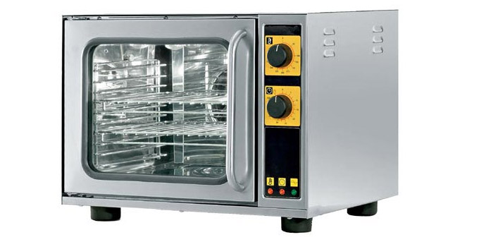 |
| Power | 2.6 kW @ 230 V | |
| Temp. Max. | 300 °C | |
| Weight | 21 kg | |
| Capacity | 4 Trays (330 x 260 mm) |
The original control knobs/switches have all been removed and the heater and fan each have been equipped with a zero-cross detecting solid-state relay. The relays have been mounted on the bottom sheet metal of the oven, to act as heatsink for the SSR (if necessary).
First tests with an ATmega based reflow controller have proven the capabilities of the oven to meet the ramp up and maximum temperature demands of an average reflow profile. However, due to the insulation of the oven chamber which increases its thermal inertia, simply turning off the heat will not result in cooling down. After passing the maximum reflow temperature, a quick but controlled cooldown is necessary in order to bring the solder paste back into a rigid state. Simply opening the door cannot be a solution for three reasons:
- Opening the door will produce vibrations at the point in time when the soldering paste is in the most fluid state which in turn could result in bad joins or even move parts out of placement.
- The oven has no way to control the temperature anymore in order to meet the reflow profile.
- Autonomous operation is impossible.
The software already drives a second GPIO that is for cooling. A radial fan will be mounted on the back and blow fresh cold (room temperature) air into one of the two metal pipes that come out of the oven chamber in the back. This will give the Raspberry full control over both heating and cooling and should provide the quickest and most reliable process with a DIY convectional reflow oven. We still need to figure out some kind of valve so that hot air cannot escape from the oven through the cooling system.
Oven Monitoring
Temperature Measurement
We performed tests with N4148 diodes as temperature sensors (hackish, simple and cheap approach) but it soon became clear that a reliable reflow controller would need reliable temperature measurement. The diodes were changing their characteristics too quickly and each one had a different/unstable compensation curve. More research finally led to K-type thermocouples as a solution.
MAX31855 Hardware Setup
The Maxim MAX31855 Thermocouple-to-Digital Converter (MAX6675 upgrade) performs cold-junction compensation and digitizes the signal from a K-type thermocouple. The data is output in a signed 14-bit, SPI-compatible, read-only format. It resolves temperatures to 0.25°C and exhibits thermocouple accuracy of ±2°C for temperatures ranging from -200°C to +700°C.
We have used a Adafruit MAX31855 breakout board, which was sponsored by Watterott Electronic to help our research efforts but you can also easily hack your own adapter and try to sample the chips.
| MAX31855 | RPi PIN | Rev1 | Rev2 | Schematic |
|---|---|---|---|---|
| Vin | NC | NC | 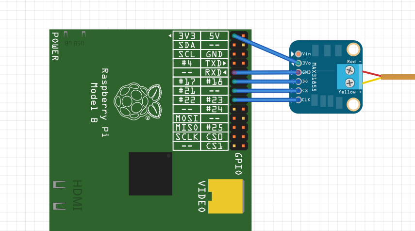 |
|
| 3Vo | P1-1 | 3V3 | ||
| GND | P1-9 | GND | ||
| DO | P1-11 | 17 | ||
| CS | P1-13 | 21 | 27 | |
| CLK | P1-15 | 22 | ||
Please check if you have a Rev1 or Rev2 Raspberry:
P1-13 is GPIO 21 on Rev1 but GPIO27 on Rev2. Since we only have Rev2 boards, the code is set to GPIO 27 by default.
Software
The picoReflow software uses the luckily already published, open-source MAX31855 python library to get the temperature from the chip.
Sensor configuration & placement
Door State
The door state (open/closed) is also covered by a microswitch connected to a GPIO (P1-12/GPIO18 & P1-14/GND) and will return the door state back to the webclient.
Oven Control
Some parts, cables and connections in the oven will carry and expose live 230V. It should be obvious that you make sure, that the oven is unplugged before connecting the control SSR or Triac to prevent electric hazards.
Heating
Load Wiring
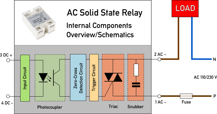
Signal Wiring
SSR connected to P1-23
| PullDown Connection (default) | PullUp Connection (alternative) |
|---|---|
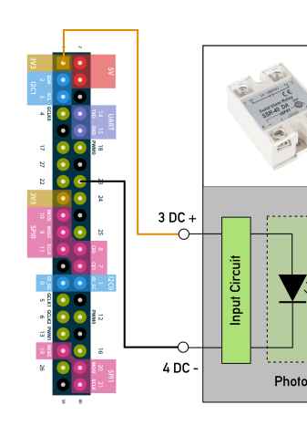 | 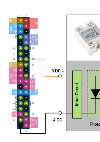 |
The default configuration has historically been to use the PullDown config, which results in an inverted control logic: When you pull GPIO23 low, the heater is switched on and when you pull GPIO23 high, the heater is switched off.
Please keep in mind that you'll have to have some script/code in your setup that makes sure that GPIO23 is pulled high as soon as the system has booted (to be sure the heater is off) or change your setup to PullUp configuration instead, if you don't want to worry/bother.
Cooling
MOSFET connected to P1-19
Fan
SSR connected to P1-21
In the current software implementation is a 200°C cut-off for the fan. As soon as the temperature rises above it, the controller will disable the fan in order to minimize vibrations while the solder paste is in fluid state. We will have to A/B test if this is necessary or not but for now it's implemented.
Software
Although picoReflow seems to become ever more popular and is working fine, it has its limits in terms of flexibility and use-case adaptability: It was only modeled and catered to the parameters and constraints of a reflow soldering process.
With the help of a lot of people giving feedback and using picoReflow in the wild, it was easy to see that a more flexible, modular and powerful approach would be needed to become a fully autonomous, multi-module governing/monitoring bot for any DIY appliance. She calls herself governess but she's still not ready for anything yet but it's progress. More appliance/module/driver/task modelling/linking will be required. It has to be totally data-driven in order to offer any useful flexibility.
With the switch to angular/ionic2 almost everything that had been done in angular1 in the meantime was useless and had to be re-implemented, a few concepts prevailed though and a rough client mock is the only thing that has been done so far while waiting for angular/ionic2 crowd to settle a bit into stable before cracking the tough nuts. So far a lot of the desired features are already mocked or in the process of implementation but the server will need to be a complete re-implementation as well. So, as long as it's only me I can only do so much in this time. Any helping hacker brain with python and/or angular2/ionic2 skills or the will to acquire them (learning by doing) is invited to join and help, we have all the tools & infrastructure needed to do remote hackathons as well.
- Rough Dev-Notes on https://apollo.open-resource.org/pad/picopid
- Make sure to check-in again and/or subscribe the RSS Feed
Screenshots of new the interface (Profile-Editor)


Dependencies
We've tried to keep external dependencies to a minimum to make it easily deployable on any flavor of open-source operating system. If you deploy it successfully on any other OS, please update this:
Currently tested versions
- python2.7
- greenlet-0.4.2+
- bottle-0.12.4+
- gevent-1.0+
- gevent-websocket-0.9.3+
Ubuntu/Raspbian
$ sudo apt-get install python-pip python-dev libevent-dev
$ sudo pip install ez-setup
$ sudo pip install greenlet bottle gevent gevent-websocket
Gentoo
$ emerge -av dev-libs/libevent dev-python/pip
$ pip install ez-setup
$ pip install greenlet bottle gevent gevent-websocket
Installation & Usage
Clone the sources from github
$ git clone https://github.com/apollo-ng/picoReflow.git
Create the initial config and start the server
$ cd picoReflow
$ cp config.py.EXAMPLE config.py
$ ./picoreflowd.py
Point your browser to 127.0.0.1:8081
Repository & Issue Tracker
Screenshots
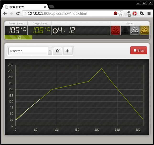
Running Reflow Job
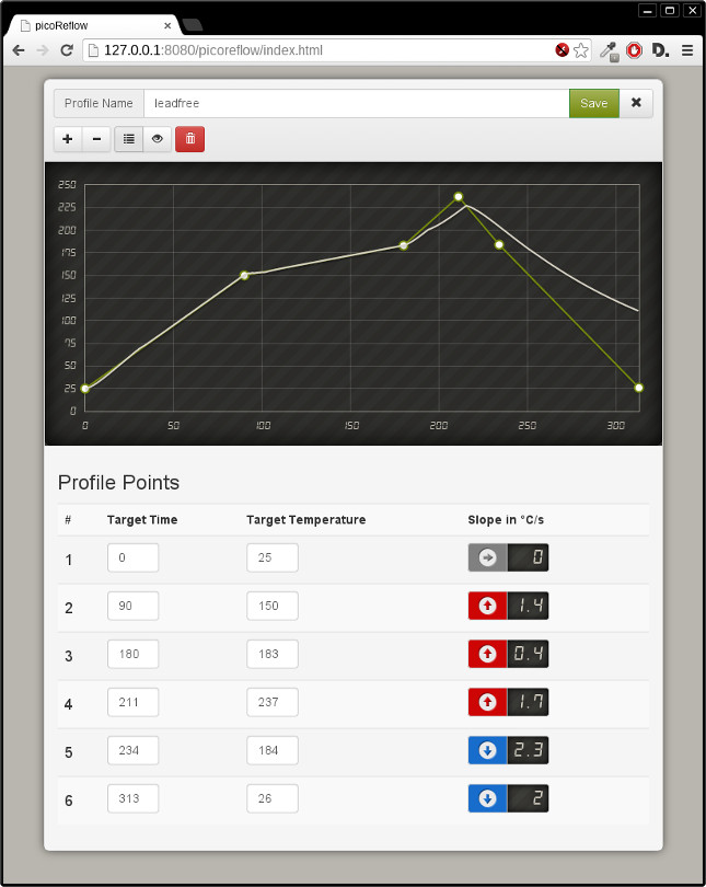
Curve editor
With the curve editor you can change existing and create new temperature curves. Just drag the points in the graph to the position you want and drop or use the text fields below to enter specific values manually. The resulting slopes are calculated automatically for convenient datasheet comparison.
Simulation
In order to get more realistic temperature values during software development and testing, without actually having to run or even have an oven, we have implemented a temperature simulation module which is active automatically, when no temperature sensor is found.
Parameters
The following thermal parameters are the basis to simulate the energy flow from the heating element through the oven and finally into the environment.
| Parameter | Unit | Example value | Explanation |
|---|---|---|---|
| <x 14>T_env</x> | °C | 25 | Environment temperature |
| <x 14>C_heat</x> | J/K | 100 | Thermal capacity of heating element |
| <x 14>C_oven</x> | J/K | 2000 | Thermal capacity of oven |
| <x 14>P_heat</x> | W | 3500 | Heating power |
| <x 14>R_oe_nocool</x> | K/W | 1.0 | Thermal resistance between oven and environment (cooling disabled) |
| <x 14>R_oe_cool</x> | K/W | 0.05 | Thermal resistance between oven and environment (cooling enabled) |
| <x 14>R_ho_noair</x> | K/W | 0.1 | Thermal resistance between heating element and oven (circulation disabled) |
| <x 14>R_o_air</x> | K/W | 0.05 | Thermal resistance between heating element and oven (circulation enabled) |
Calculation
Every <x 14>\Delta t</x> the following calculations are performed:
Thermal energy flowing into the heating element:
<x 14> Q_h = P_heat * \Delta t </x>
Temperature change of heating element by heating:
<x 14> \Delta T_h1 = Q_h / C_heat </x>
Temperature change between heating element and oven:
<x 14> P_ho = (T_h - T) / R_ho </x>
<x 14> \Delta T_1 = (P_ho / C_oven) * \Delta t </x>
<x 14> \Delta T_h2 = - (P_ho / C_oven) * \Delta t </x>
Temperature change between oven and environment
<x 14> P_oe = (T - T_env) / R_oe </x>
<x 14> \Delta T_2 = - (P_oe / C_oven) * \Delta t </x>
Temperature of oven and heating element at this timestep:
<x 14> T = T_old + \Delta T_1 + \Delta T_2 </x>
<x 14> T_h = T_h_old + \Delta T_h1 + \Delta T_h2 </x>
picoReflow in the Wild
This project already has inspired a couple of people who are using this concept and free software stack for their own purposes:
DIY Reflow Toaster


- The domain seems to have gone offline, there is a snapshot on archive.org
Ararpi Reflow Oven

Moore Bros Composite Oven

A custom built oven to bake carbon composite parts.
