Table of Contents
HOWTO - GL-Inet 6416 External Antenna Hack
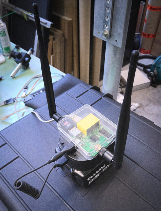
Since a lot of people continue to show interest in hacking their ML-3020 with an external antenna it was time to show how to do it for the GL.Inet 6416. The following modifications can be done in 5-10 minutes, give you a stable RP-SMA connector and have been tested and running here on 5 units without any problems.
Preparation
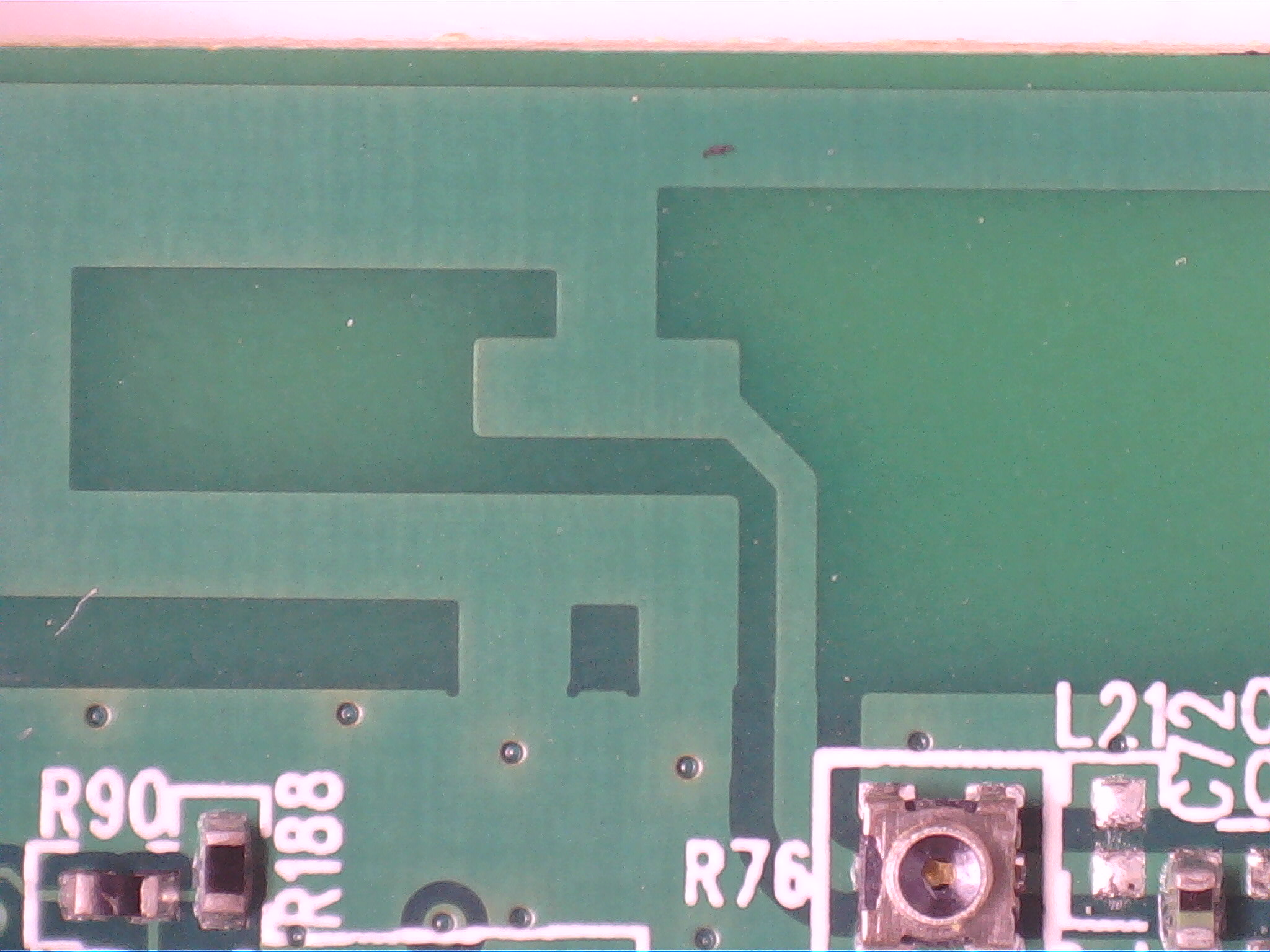
Locate the onboard PCB antenna structure
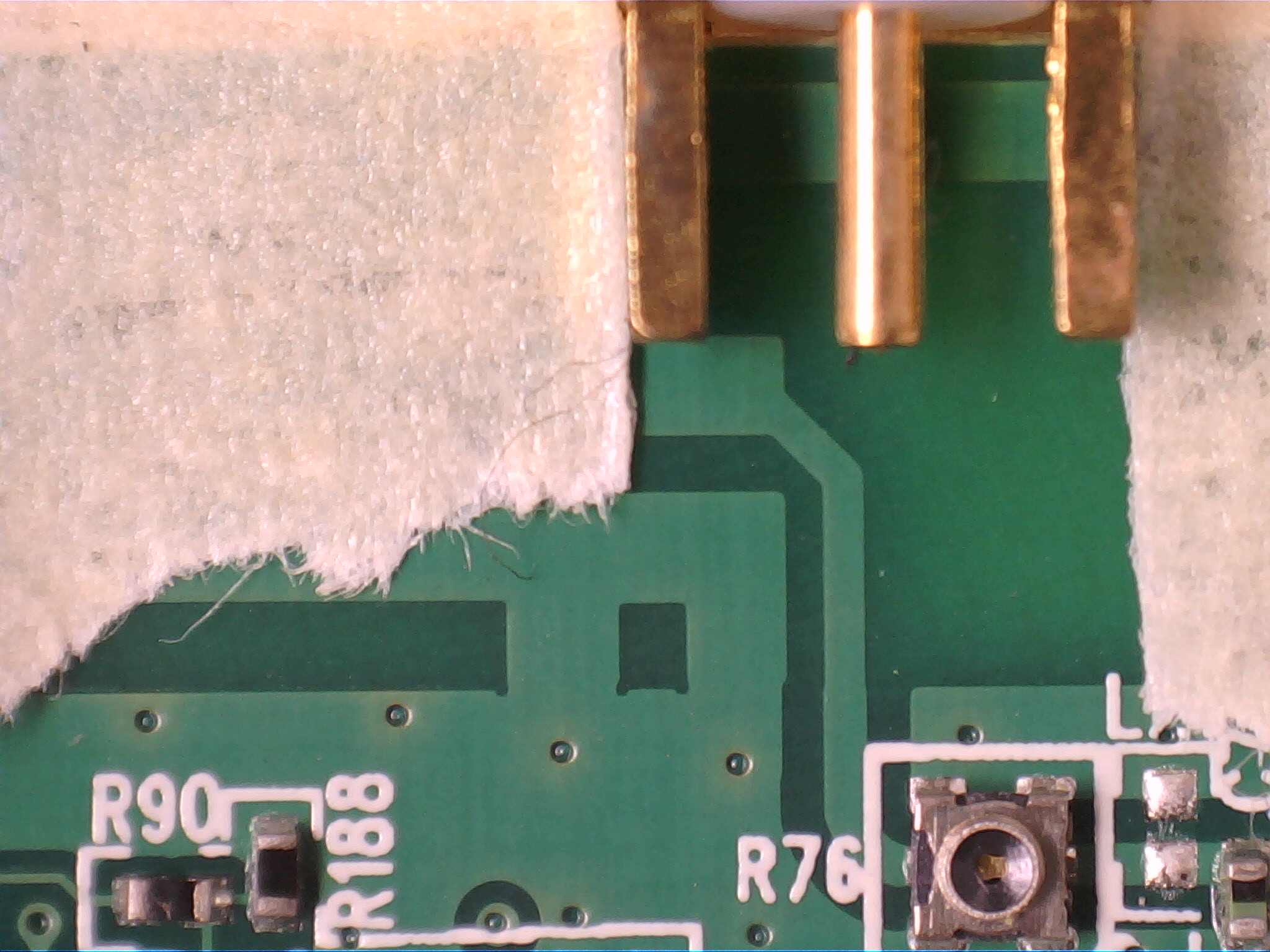
Align PCB edge RP-SMA connector
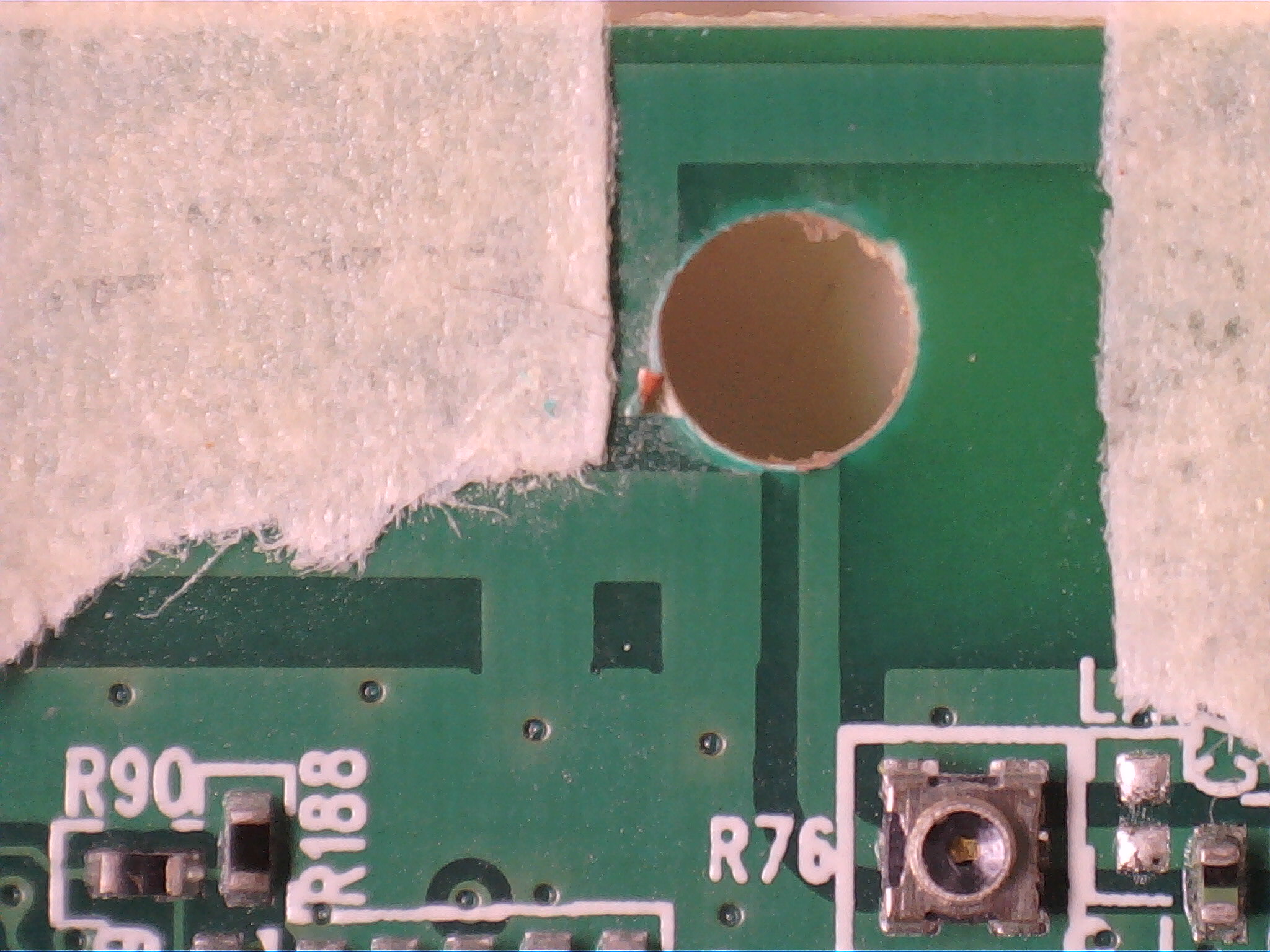
Use some tape to mark the sides of the connector in place
Mechanical
Use a 3mm drillbit to disconnect the antenna trace from the groundplane.
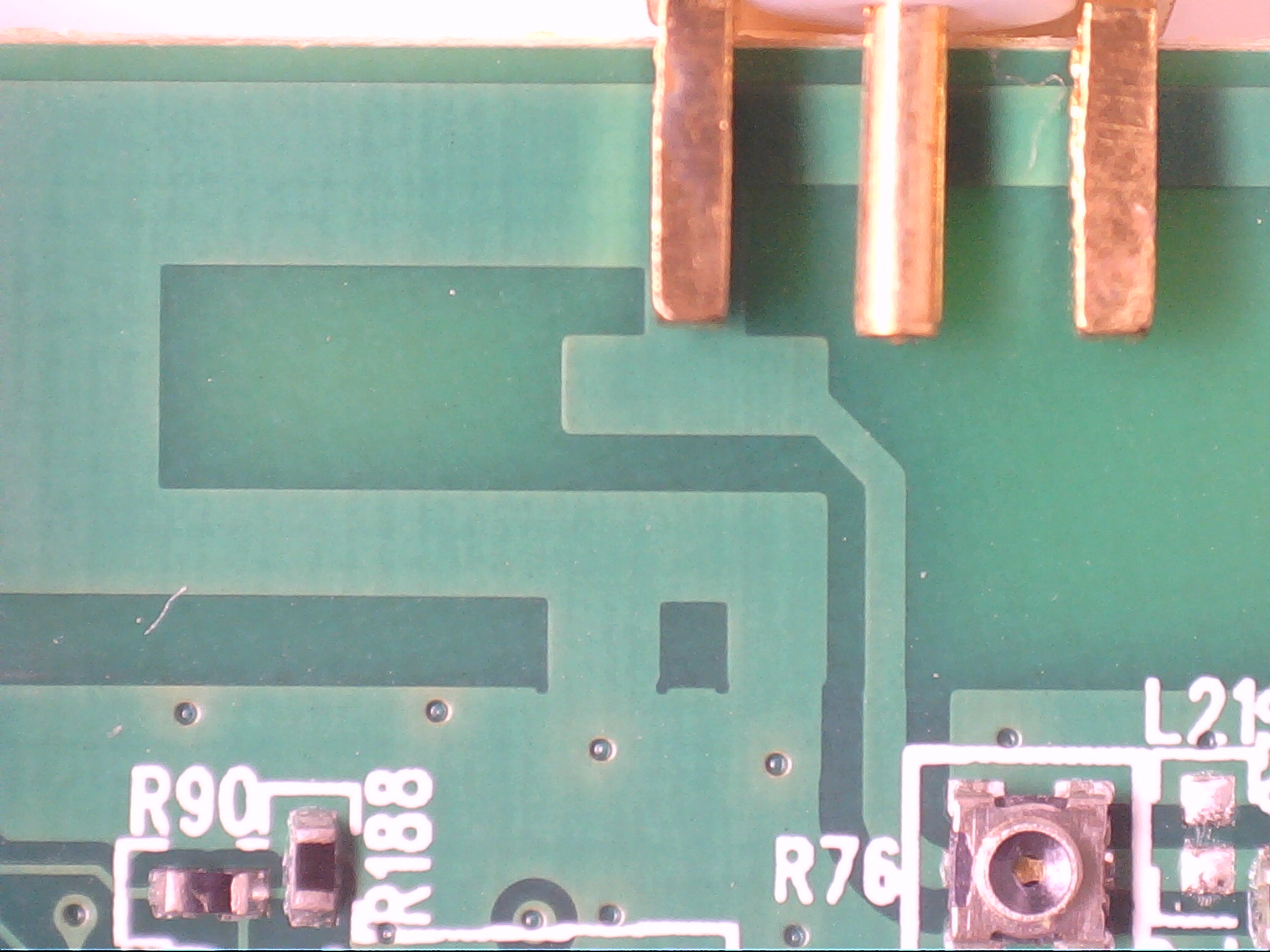
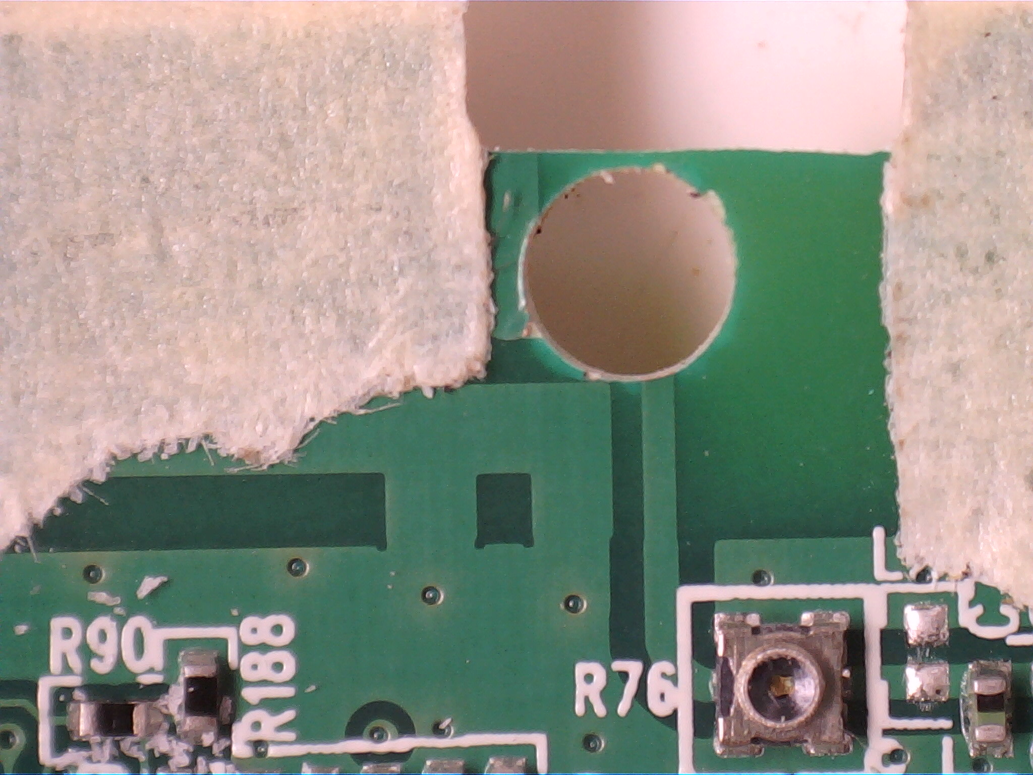
File the pcb along the tape marks until the rp-sma connector just reaches the edge of the PCB
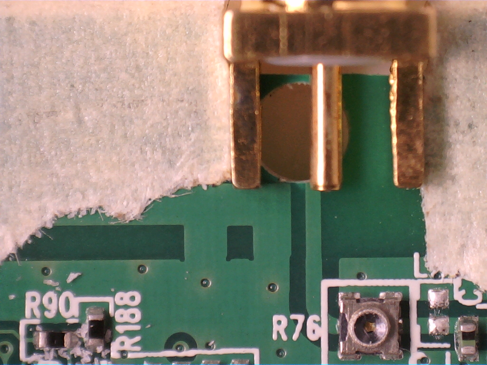
Verify that the center pin will reach the antenna trace
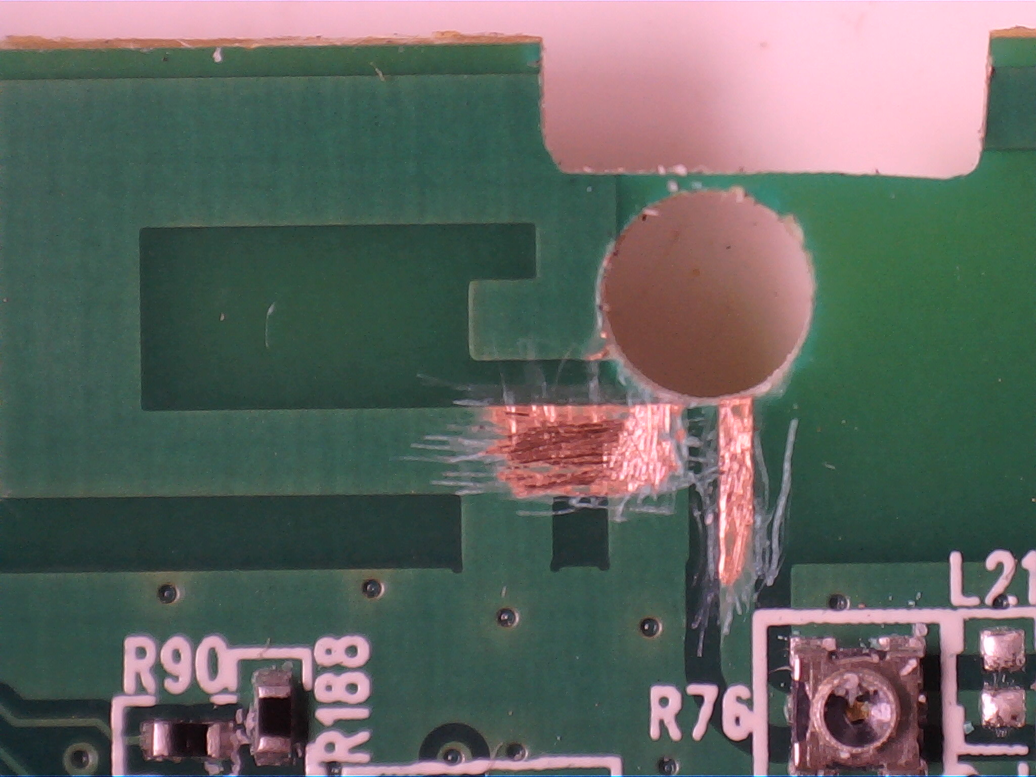
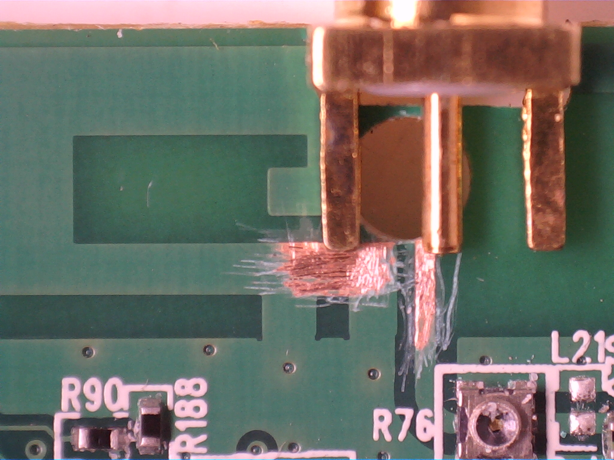
Carefully remove the soldermask to be able to solder signal and ground.
Re-Verify that ground and signal pins actually reach the copper to make soldering easy.
Soldering
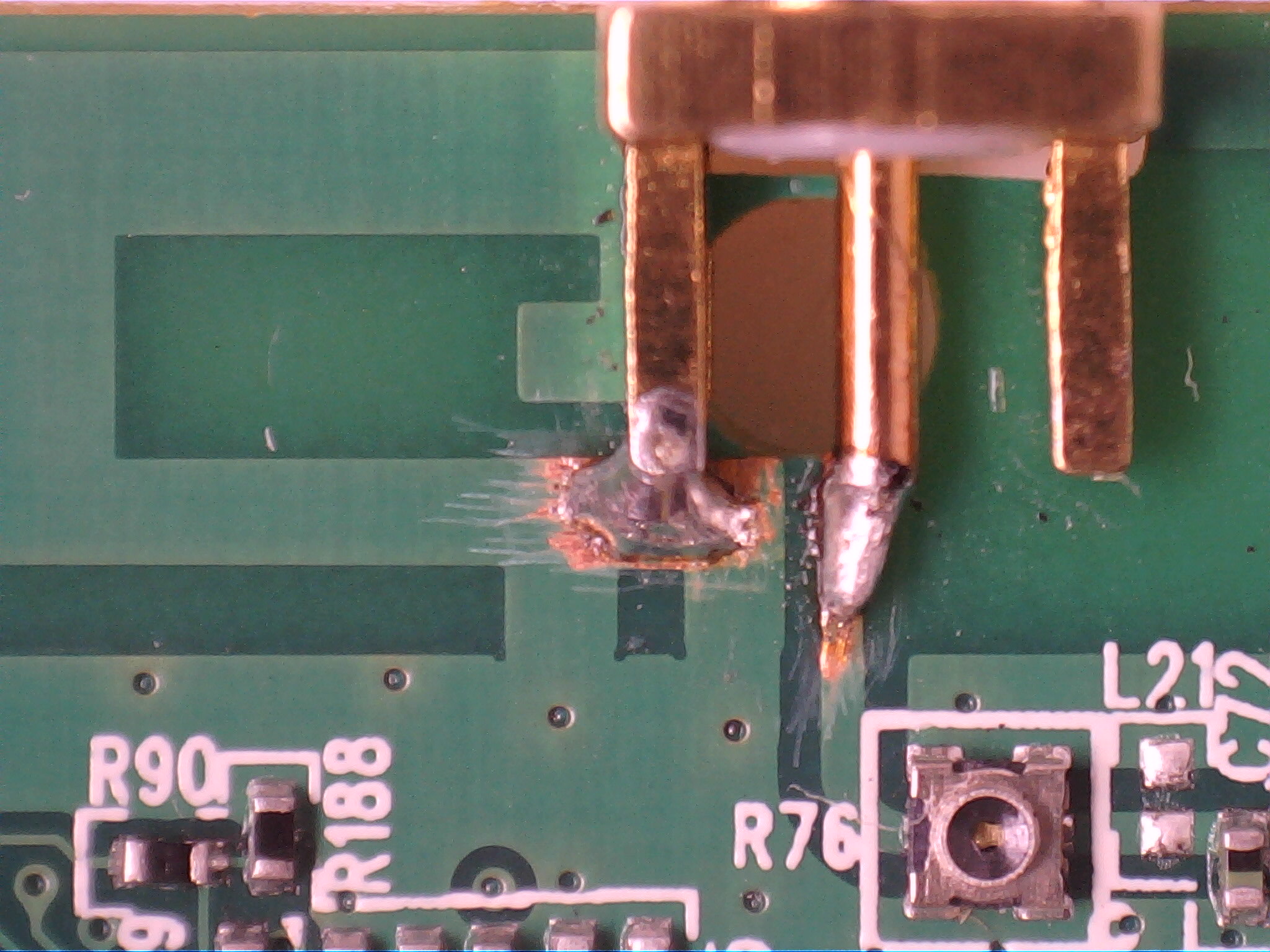
Now it's time to solder the center and ground pin. Don't use too much, it only needs to be connected. This is important, you may have a great solder blob there that may seem stable but one heavy turn with an external antenna in 90° position will just rip off the traces of the PCB. One of our MR-3020 was lost in experiments because this was totally underestimated.
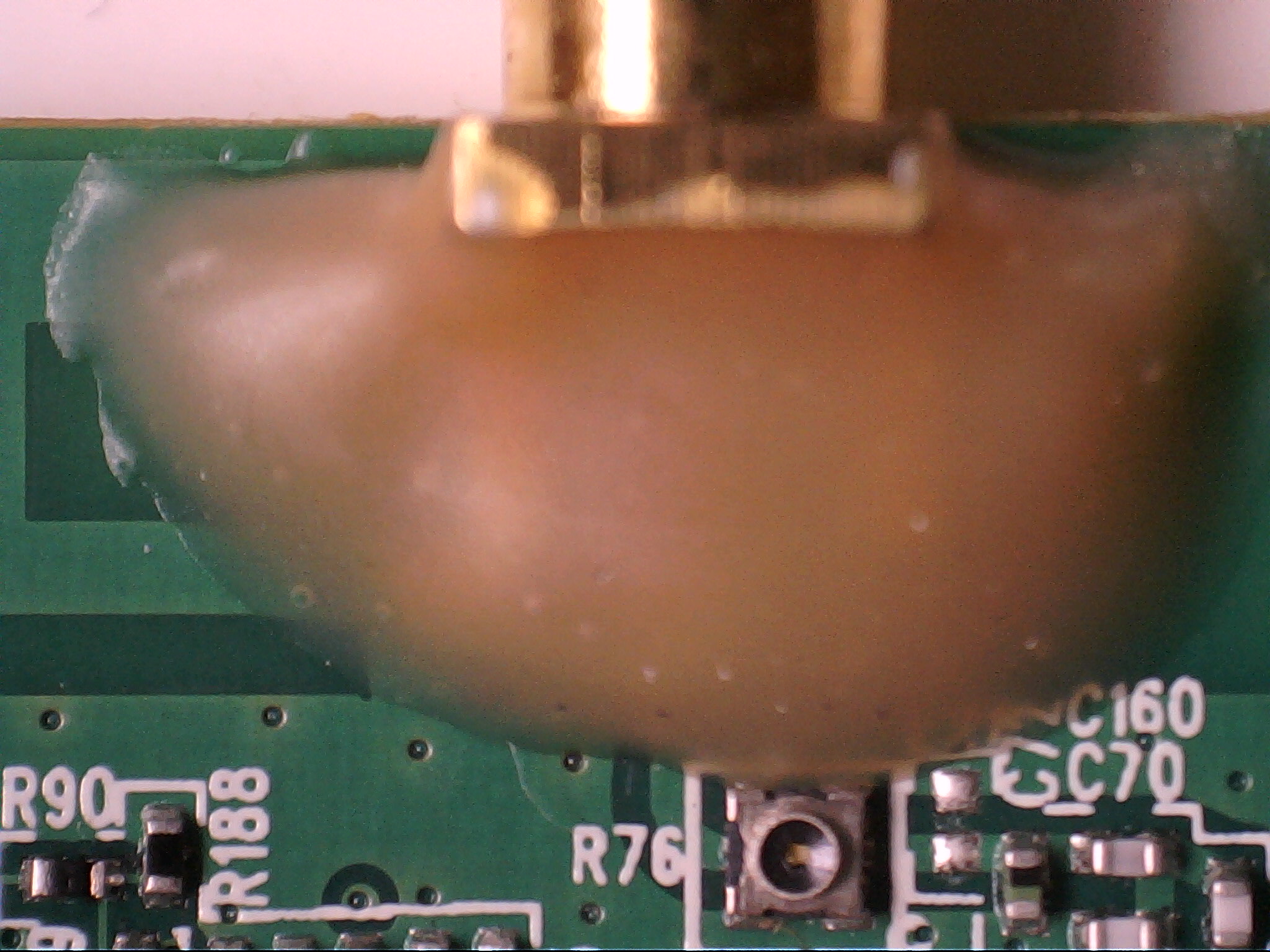
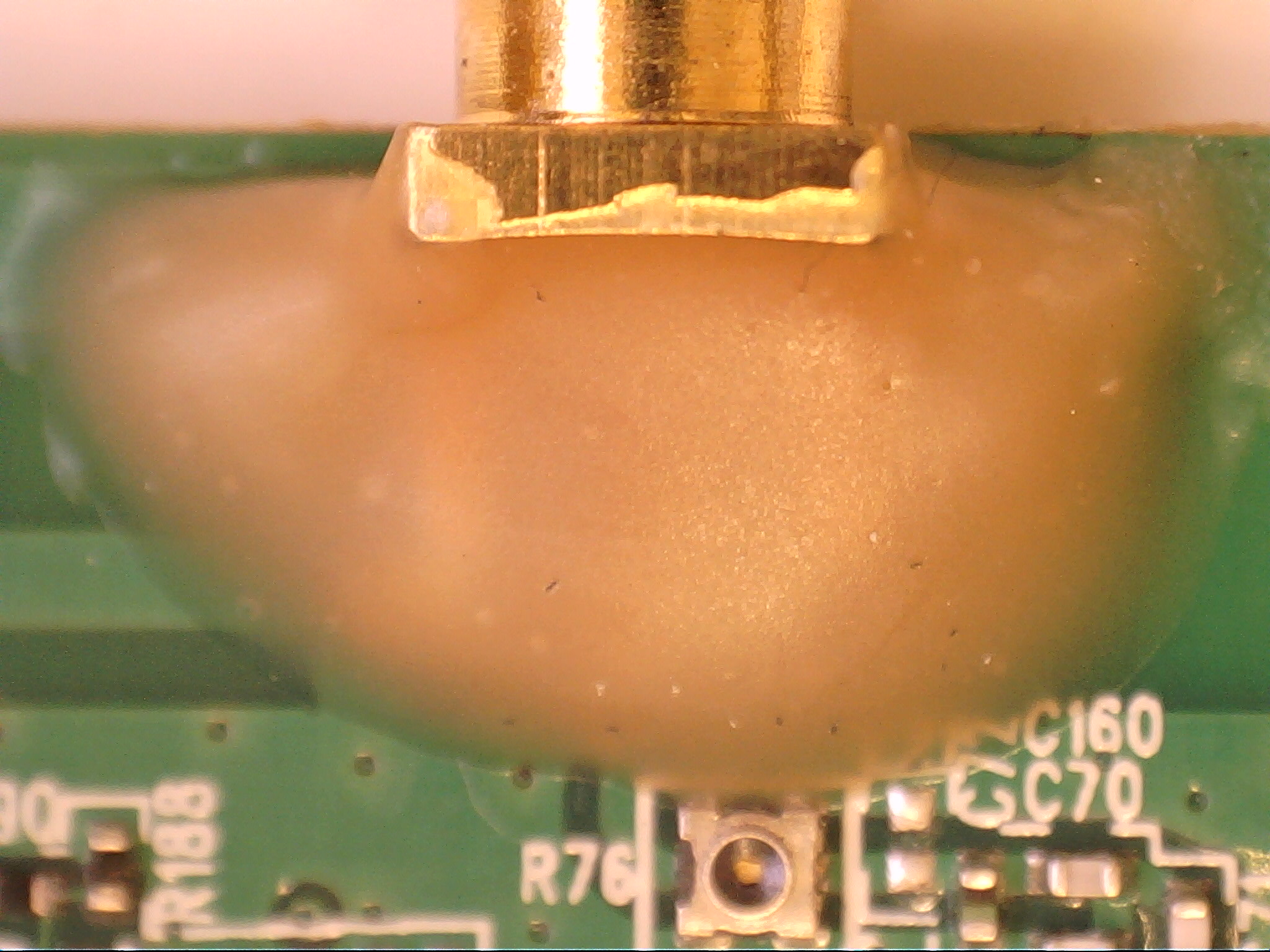
Remove any solder flux residue and continue with the final task of putting some glue in there for stability.
