Table of Contents
Rotors
Compared to drag-only type rotors (Savonius), lift-only type rotors (Darrieus) have been proven to be generally less suitable for low wind environments since they're difficult to start up. The maximum speed of drag-only type rotors is always lower than a comparable lift-only type rotor, because a lift-only type rotor can rotate faster than the wind speed at the tips but with less torque. However, the Gorlov rotor with a NACA 0015 airfoil may be a very well suited lift-type rotor for small-scale, low wind environments.
A drag-only type rotor can develop more torque, even at early stages in low wind conditions, but that would require a very specific and resource-intensive generator to accommodate for the very low rotational speed. A typical low end for a direct driven axial flux permanent magnet alternator with many poles is about 100 revolutions per minute. Everything under 100 rpm means huge additional resource investments into rare earth magnets and loads of copper (windings).
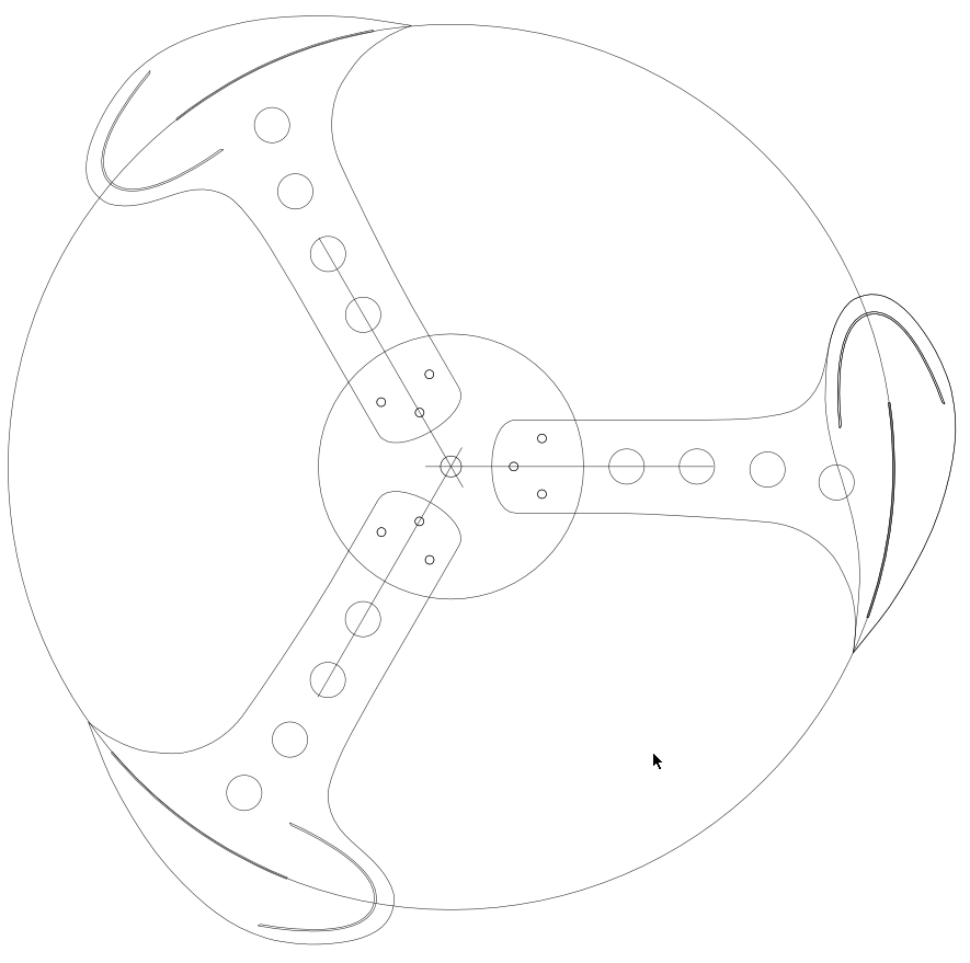
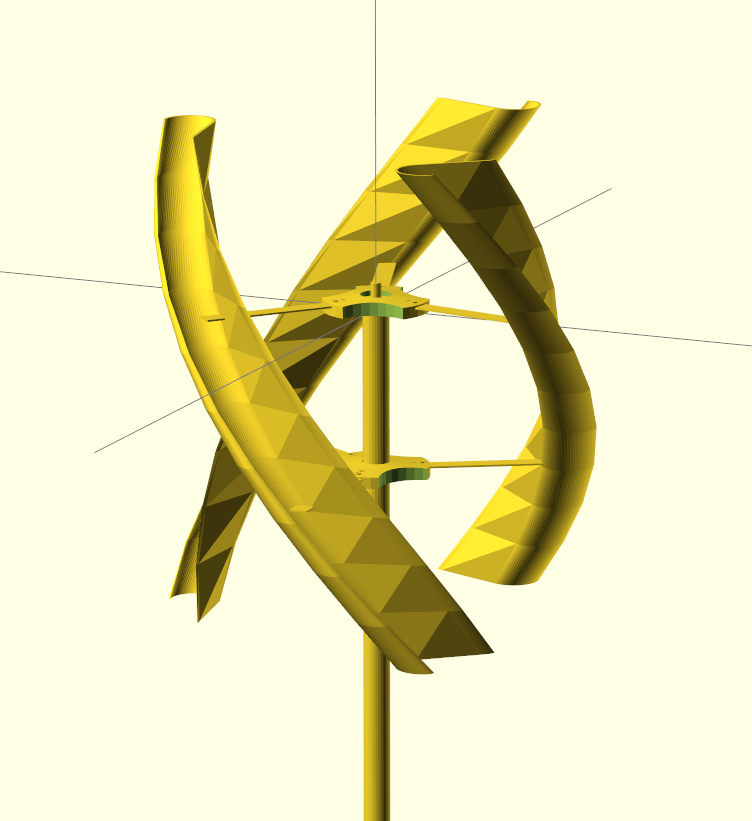
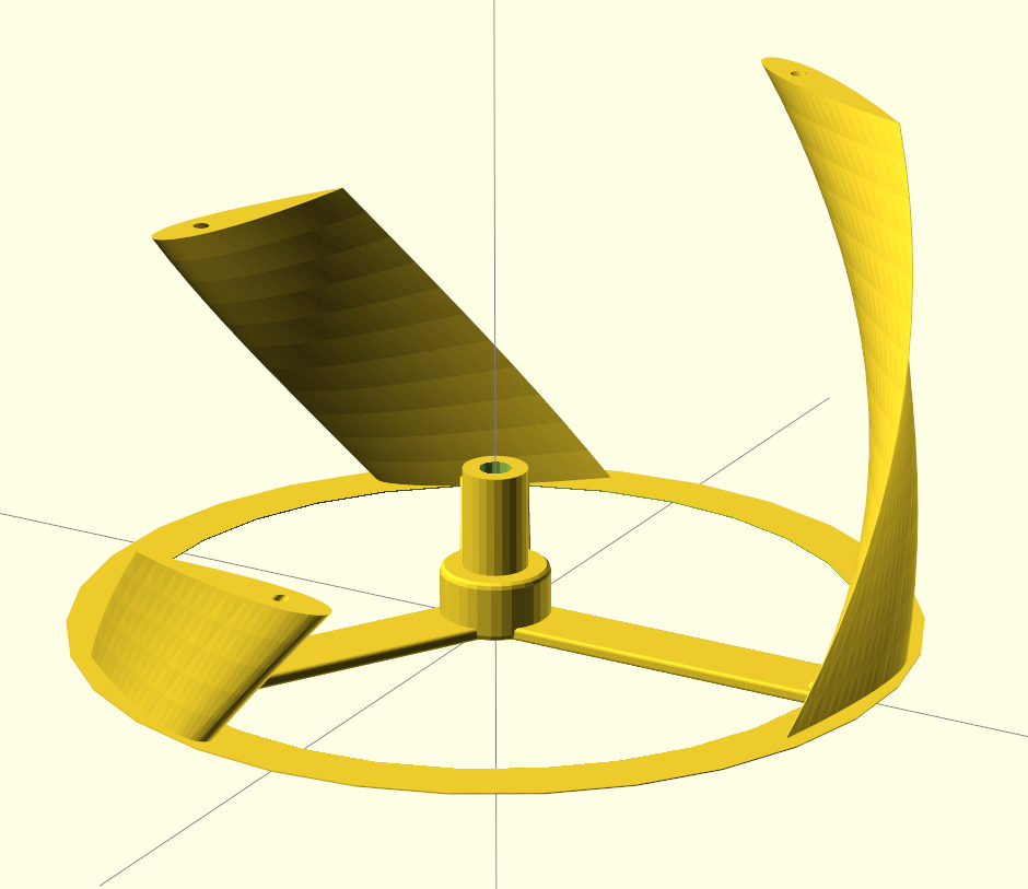
VAWT Rotor Types
| C-Rotor | Lenz-Rotor | Gorlov-Rotor |
|---|---|---|
 |  |  |
| Laser Cut | 3D Print (complex multipart) | 3D Print (print 2 - assemble 1) |
| 10-50 W | 5-40W | <5 W |
Sources: https://github.com/apollo-ng/eXperimental-Turbines
The Gorlov Helical blade type is a derivative of the Darrieus blade type, originally developed by its namesake Alexander M. Gorlov to be used in hydro-power applications. It attempts to solve the problems of vibration and noise in the original Darrieus design by having helical curved blades as opposed to straight blades. In the traditional Darrieus setup, as the blades rotate the angle of attack will change, resulting in areas throughout the rotation where the blade is in a stall. This causes vibration which will reduce the life of the turbine, along with causing noise which is especially unwanted in urban settings. The Gorlov blade type, on the other hand, is curved in a helical fashion, which means that throughout its rotational path, at least part of the blade will not be in a stall, which greatly reduces the vibration and the noise generated.
Additionally, there should be a design for a very simple H-Rotor made of half DN100-PE-tubes (standard sewer piping tubes) as wings, preferably three or 3 x n wings for very low resource budget projects.
Standard-Parameters
Standardization of the system and compatibility of components offers a perfect test environment for different rotor types to see how comparable rotor-surfaces will perform with different rotor-types in the same environment.
Maximum wind speed
| IEC wind class | 50-year-maximum | Average wind speed |
|---|---|---|
| I | 50 m/s | 10 m/s |
| II | 42.5 m/s | 8.5 m/s |
| III | 37.5 m/s | 7.5 m/s |
| IV | 30 m/s | 6 m/s |
Example for a classification in Germany, Berlin, Cologne, Karlsruhe: The mean wind speed is classified above IEC class IV with an average value of 2.3 - 3.6 m/s at ground level (equals a mast height of 10 m or below) without any obstacles.
IEC classes are realistic for higher wind zones, industrial wind turbines usually sit at >50 m. We are safe with an IEC class IV design.
Maximum size
Each assembly should have a rotor surface no larger than 4m² to avoid possible legal restrictions in Europe. A wind surface of 4 m² equals a 2 m diameter VAWT rotor with a height of 2 m.
In every wind condition, a 1 m diameter VAWT with a height of 4 m is more efficient due to the higher rpm and better aerodynamic figures. Industrial VAWTs aim for a large height, not for a large diameter.
Optical Environment Integration
Each assembly should be matte painted in order to avoid irritation of people in the neighborhood by re-occurring reflections of direct sunlight by shiny rotating blades into the surrounding area. Additionally, the color itself should be visually in-obtrusive, to reduce the risk of people objecting to the turbines in the neighborhood, just because of prominent visual distractions. The following matrix gives a good overview, to choose from a commonly used range of colors for specific locations, to make it as invisible as possible.
| General Area | White | Light-Blue | Light-Grey | (Light) Grey-Green |
|---|---|---|---|---|
| City/Urban Environments | + | - | + | (+) - |
| Free-Rural Environments | - | - | ++ | (+) + |
| Green/Forest Environments | - | - | + | (+) ++ |
| Location Specific | ||||
| Elevated/Exposed Location | - | ++ | + | (-) – |
| High-Temperature Location | ++ | + | + | (-) – |
Rotor-Interface

Basic Wind Power Calculations
Corrections and additional approaches are always welcome.
Power Estimation
The following equations provide a means to estimate the approximate amount of kinetic and electric power converted by a wind turbine:
Available power in the wind
| Parameter | Unit | Detail |
|---|---|---|
| | Watt | Available power in the wind, as kinetic energy |
| | m² | Swept area (turbine/sail etc.) |
| | m/s | Wind speed |
| | kg/m³ | Density of Air (rho) ~1.225 at 25°C |
Example: eXperimental Turbine Lenz-Rotor with 0.96 m² surface @ 4 m/s
Example values at certain wind speeds:
| Windspeed | 1 m/s | 2 m/s | 4 m/s | 8 m/s | 16 m/s |
|---|---|---|---|---|---|
| Power | 0.57 W | 4.60 W | 36.68 W | 294.91 W | 2.36 kW |
Basically, power scales linearly with the area swept out by the turbine blades and cubically with the speed of the wind as it sweeps the blades. However, these relationships have some variation depending on the design of each particular turbine.
Conversion Efficiency
→ Converted rotational energy in Watt
→ Available power in the wind, as kinetic energy in Watt
→ Power coefficient
Example: eXperimental Turbine Lenz-Rotor with 0.96 m² surface @ 4 m/s
The power coefficient accounts for the efficiency of the turbine in converting the wind’s kinetic energy into rotational energy. According to Betz's law, no wind turbine can capture more than 16/27 (59.3%) of the available kinetic energy in wind. This theoretical maximum power limit is also known as Betz's coefficient (0.593) or Betz-Limit. However, most wind turbines operate at a power coefficient of less than 0.45:
| Turbine Type | Power Coefficient |
|---|---|
| Simple drag VAWT | 0.20 |
| Decent VAWT | 0.30 |
| Good VAWT | 0.35 |
| Good HAWT | 0.40 |
| Big Grid MW+ HAWT | 0.45 |
Torque
For turbines which use drag forces (not lift forces), the following equation can be used to estimate the amount of torque in the system, where R is the radius of turbine in meters1).
Tip Speed Ratio
The tip speed ratio (λ) defines the relationship between blade tip speed and incident wind speed2).
This equation shows the relationship between the tip speed ratio and the power coefficient for various blade types. For each type, there is a unique curve, and therefore a unique optimal tip speed ratio which corresponds to the maximum power coefficient that can be achieved.
For example, a Savonius rotor will produce a maximum power coefficient of about 0.31 at a tip speed ratio of about 0.9. However, a Darrieus rotor produces a maximum power coefficient of around 0.35 at a much higher tip speed ratio of around 5.8.
To be most efficient, a blade and rotor should be designed to perform near its optimal tip speed ratio at wind speeds it is likely to encounter3).
Reynolds Number
The Reynolds number range for small-scale gorlov VAWTs is quite low. In comparison, the Reynolds number operating regime of most airfoils used for aircrafts ranges from 6.3e6 for a small Cessna to 2.0e9 for a Boeing 747.
| Parameter | Unit | Detail |
|---|---|---|
| | m/s | Incoming flow velocity |
| | m | Turbine Diameter |
| | kg/m³ | Density of Air (rho) ~1.225 at 25°C |
| | m²/s | Kinematic viscosity of Air (nu) ~1.57e-5 at 25 °C |
Example: Helical Gorlov-Rotor with 35 cm radius @ 4 m/s
You can watch these calculations in action, applied to reference wind speed measurements on the Wind Power VFCC Dashboard.
A tuned VAWT probably has a best-case efficiency of 35%, while a simple drag-based turbine with no optimization nor special aerodynamics may have an efficiency of about 20%.