Table of Contents
PiGI Hardware
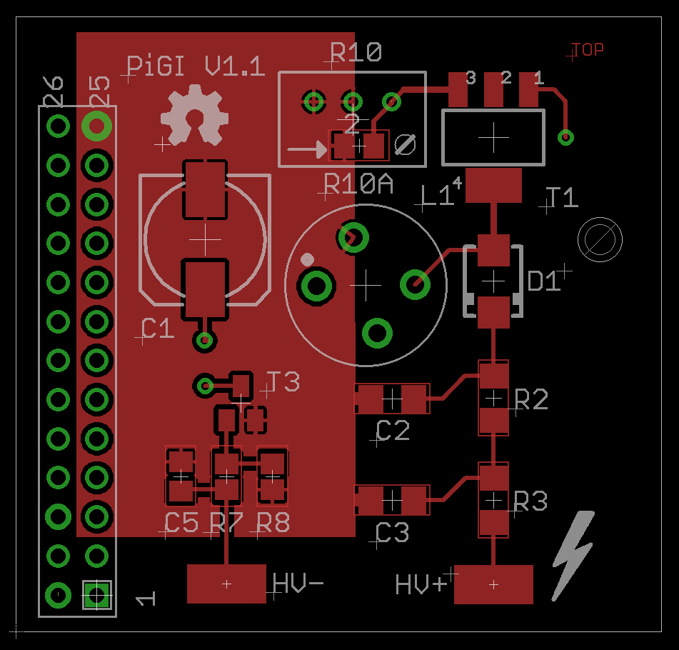
Schematic V1.1

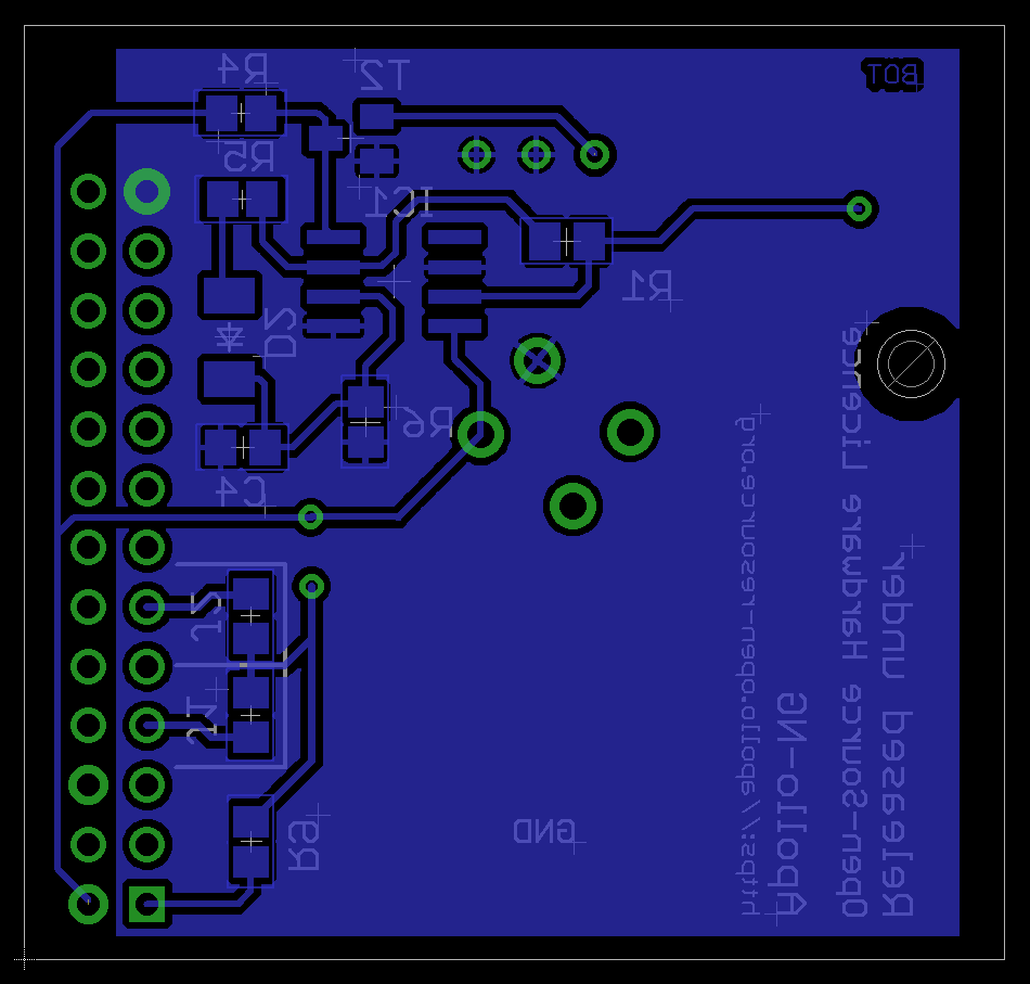
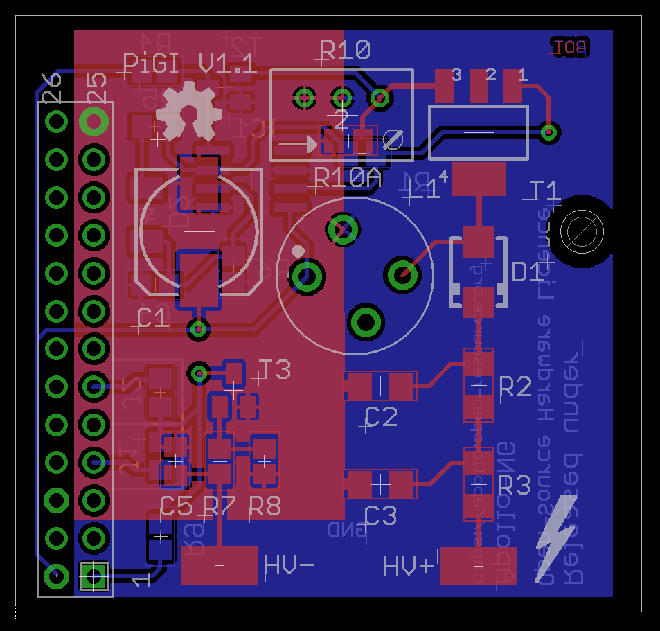
Layout V1.1
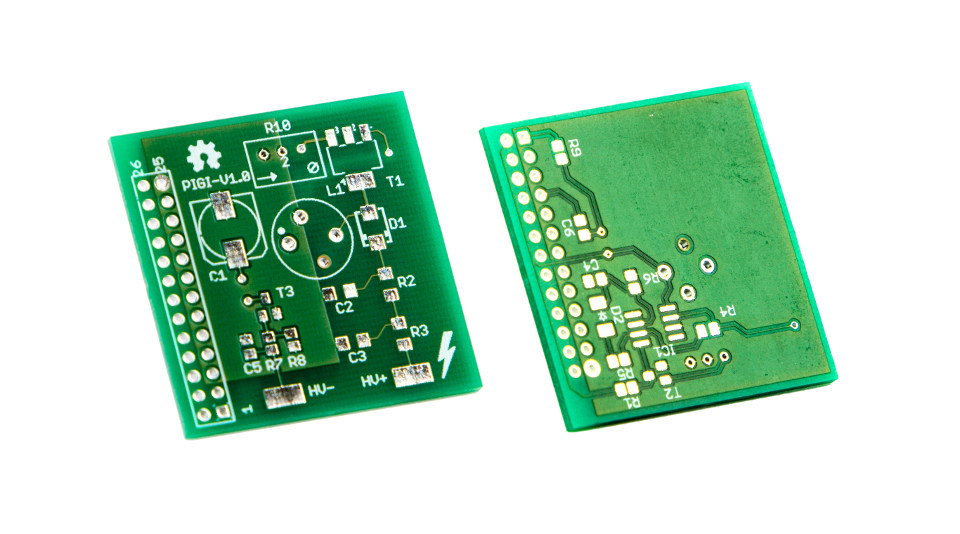
Prototype PCB's V1.0
Download Layout & Schematics (Eagle 6.2.x):
https://github.com/apollo-ng/PiGI/tree/master/hardware
Circuit Details
The Pi-GI circuit is divided into two parts:
- Kickback High-Voltage Switching Power supply
- Impulse Inverter
Inductive Kickback Switch Mode Power Supply
The basic idea was to build a cheap but efficient Kickback High-Voltage Generator to convert 5V up to 450V - 600V in order to reliably feed almost any available Geiger-Mueller tube for maximum flexibility & hackability. This circuit design was inspired by Tom Napier's article in Nuts & Volts, Jan 2004 (rebuplished in issue #184 of Circuit Cellar Nov 2005) which has been used successfully in multiple DIY Geiger-Counter projects worldwide for example:
Since the original circuit incorporated some expensive and hard to get Through-Hole parts (like the STX13005 & UF4007), it was redesigned with modern and available SMT components. This also led to an increased tolerance of the high voltage components up to 1kV instead of 600V. The great thing about this design is the really low BOM count and the fact that it regulates the HV really well WITHOUT the need to have feedback from the HV rail.
How does it convert 5V up to 500V and more?
The transistor (T1) is turned on and current flows into the inductor (L1). When the transistor is turned off, the input current that formed and maintained the inductor's core magnetic field becomes zero. The magnetic field collapses causing a voltage reversal to occur in the inductor and induces sufficiently high voltage (known as inductive kickback voltage) into the diode (D1). If you want to learn more about it and use a java-enabled browser you can use this inductive kickback simulator. Toggle the switch at the bottom (simulating T1) and watch the voltage graphs to see the effect.
For the HV generator only two components seemed to be critical:
| Component | Function & Parameters | Selected Part |
|---|---|---|
| D1 | Fast recovery diode (75ns) for up to 1kV | BYG23M |
| T1 | NPN transistor with a >=1kV collector-emitter breakdown voltage | STN0214 |
The inductor is a high Q wound dust core choke with shielding to minimize EMI. The output voltage is set by the maximum current, which is controlled by the adjustable trimmer (R10) in the emitter lead of the STN0214. A lower resistor value (turning CCW) will result in higher output voltage. Alternatively, when only a certain type of GMT is going to be used with a PiGI module, R10 can be replaced with R10a to set the specific required voltage for the GMT. Please add working values for R10(a) with your particular tube to the common-geiger-tube-parameter.
Based on the CMOS 555 The 555 oscillates at about 3.2 kHz Pulse on time is controlled by the inductor and emitter resistor (which sets the maximum current), which in turn sets the high voltage value.
Impulse Inverter
Each impulse will pull the selected (J1/J2) GPIO pin to ground via T3 so that it's possible to generate an interrupt which can be counted. This ensures the safety of the PI and also helps to prevent getting false events generated by external EMI.
Prototype & projected production costs
| Volume | PCB | Parts | Soldering method | Risk margin | Final product |
|---|---|---|---|---|---|
| 7 V1.0 Prototypes | EUR 7,23 | EUR 8,67 | Hand (EUR 0) | — | EUR 15,90 |
| < 100 V1.1 | EUR 4,97 | EUR 9,70 | Hand (EUR 0) | 20% | TBD |
| >= 100 V1.1 | EUR 2,79 | EUR 7,05 | Outsourcing (TBD) | 15% | TBD |
| >= 1000 V1.1 | EUR 0,70 | EUR 3,95 | Outsourcing (TBD) | 10% | TBD |
As we can see, it scales very well with numbers and a non-profit oriented production run could bring many modules to people for less than 20 EUR. If it were sold for more than 25 EUR (fully assembled), someone would really be ripping people off.
Assembly Instructions
BOM
Check the Mouser project page for specific lists and datasheets. You can also directly order all parts with one click from there:
Recommended Hand Solder Order
Bottom
| # | V1.0 | V1.1 | Part/Value | Package |
|---|---|---|---|---|
| 1 | D2 | MMSD4148 | ||
| 2 | C4 | 1nF | 0805 | |
| 3 | R5 | 330 ohms | 0805 | |
| 4 | R1 | R4 | 100k | 0805 |
| 5 | R6 | 220k | 0805 | |
| 6 | R4 | R1 | 1k | 0805 |
| 7 | R9 | 27k | 0805 | |
| 8 | IC1 | TLC555QDRQ1 - Case mark facing towards R6 | SOIC-8 | |
| 9 | T2 | MMBT4401 | SOT-23 | |
If you're not stacking two modules use either a 0-ohm resistor/solder-bridge on J1 or a capacitor to connect the GPIO Pin of the PI to the inverter's collector. Don't use a capacitor when connecting to a uC with internal pull-up (like a Raspberry Pi).
When you want to stack two modules, connect J1 on the lower and J2 on the upper module.
Top
| # | V1.0 | V1.1 | Part/Value | Package |
|---|---|---|---|---|
| 1 | C5 | 330pF | 0805 | |
| 2 | R7 | 1.5k | 0805 | |
| 3 | R8 | 100k (default - see signals for other values) | 0805 | |
| 4 | T3 | MMBT4401 | SOT-23 | |
| 5 | C1 | 220uF/10V LowESR Aluminium Electrolytic Capacitor | see BRD | |
| 6 | C2 | Vishay MLCC 10nF/1kV | 1206 | |
| 7 | C3 | Vishay MLCC 10nF/1kV | 1206 | |
| 8 | R2 | KOA Thick Film 1M 0.25W 0.5% | 1206 | |
| 9 | R3 | KOA Thick Film 4.7M 0.25W 1% | 1206 | |
| 10 | D1 | Vishay BYGM23 Fast Recovery Diode 1.5A/1000V/75ns | DO-214AC (SMA) | |
| 11 | T1 | STN0214 Bipolar NPN 1k2V | SOT-223 | |
| 12 | L1 | Murata Shielded Inductor 15mH | see BRD | |
| 13 | R10 | Bourns Trimmer 100R | see BRD | |
| * | — | R10a | optional, with a fixed value instead of R10 | 0805 |
| 14 | H1 | Stacking Raspberry Pi Header | 2×13 2.54mm | |
Test Points
High Voltage
The kickback power supply is very efficient (in order to draw less power) and the whole setup is tuned very much to accommodate a geiger-mueller tube as a power consumer. Introducing another consumer (a multimeter with 10 Megaohm for example) draws too much current from the circuit.
The supply drops down and we can only see significantly lower voltage values. To mitigate the effect a high value resistor (1 Gigaohm) was used to obtain a somewhat more reliable measurement. The perils, pitfalls and possible solutions to measuring the high-voltage (with some accuracy) and alternative methods to adjust the high-voltage without measurement are described here.
Benchmarks
This test was run on a V1.0 prototype board, plugged into a Pi with running counterd. A radioactive test source (thorium) was placed in front of a FHZ-76 tube. The high-voltage was increased (turning R10 counter-clockwise) until the count-rate reported by counterd didn't increase anymore. The following table shows the resulting measurement of the set voltage using different setups:
| Resistor Setup | Read Voltage | Calculated Voltage |
|---|---|---|
| 10M (Fluke-87V internal resistor) | 230V | 230V |
| 10M + 42.3M (9x 4.7MOhm in series) | 63.7V | 333V |
| 10M + 1G (20kV 1 GigaOhm single resistor) | 4.56V | 460V |
Measured at: [+] Cathode of D1 (pin facing towards R2) [-] Cathode of GM Tube (HV- Pad)
Calculation
Formula
Examples
Signals
")
555 output: Via next to T1
Tube
It seems, that in practice (industrial/military), cathode connection is always supposed to be used with GM tubes if possible, mainly because it's less likely to affect the characteristics of the tube and reduces undesirable effects. The extra capacitance of the output circuitry added to the cathode is considerably less significant than when added to the relatively small anode. This was taken into consideration while designing the PiGI.
For optimal tube operation R3 (anode resistor) and the equivalent of R7/R8 (cathode resistor) should have a 45:1 Ratio, at least that seems to have become “industry standard”. A short test with the LND712 GMT showed that indeed the signal flanks became a bit more precise when R8 is 220k instead of 100k in order to match the 10M for LND 712. However, in many other tests the circuit has shown a very high resilience against “suboptimal” operating conditions.
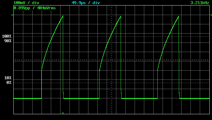
Worst Scenario (Undervoltage & very high anode/cathode resistor ratio mismatch)
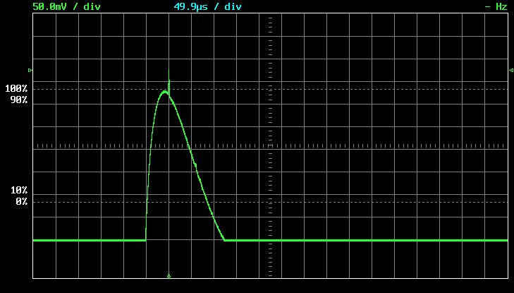
Recommended operating voltage & 45:1 anode/cathode resistor ratio
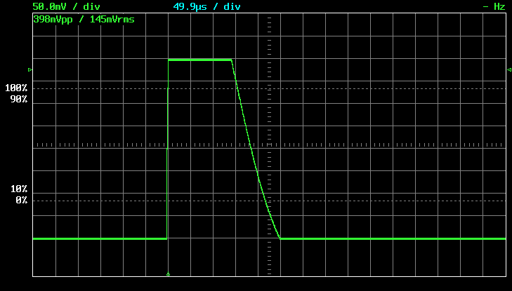
GPIO output
This is how the final impulse signal looks like to the counting IO Pin. It also leaves a question: For the LND 712 the dead-time is supposed to be 90us, but when you count the divs in the scopeshot above it is about 140us. Shouldn't in this case 140us be used as a base value for the dead-time algorithm?

Radioactive Test Sources
Since everything is over-regulated these days, up to the point where only multi-national-corporations can obtain the resources needed to develop something easily, it's quite a challenge to find radioactive test sources to probe a Geiger Counter with more than just the local dose rate. So instead of having simple access to quality test-radiators which can be handled and stored in a safe manner, we have to improvise and hack something out of whatever we can find. When we consider that the regulation's original intent has to protect of people from harm, it backfired pretty well.
The mightyohm blog has compiled a list of things you can try to use:
http://mightyohm.com/blog/2012/02/feed-your-geiger-readily-available-radioactive-test-sources/